{1,2,3,4}

(This is wonderfully obtuse, but amused me :)

Neil Henning (@sheredom) asked:

SPU gurus of twitter unite, want a vector unsigned int with {1, 2, 3, 4} in each slot, without putting it in as elf constant, any ideas?

Interesting question. The SPU ISA generally doesn’t help build vectors with different values in each slot. In this case, there are only very small values required in each register, so it can be done with a neat little trick.

My answer:

    fsmbi r4, 0x7310  # r4 = {0x00ffffff, 0x0000ffff, 0x000000ff, 0x00000000}
    clz r5, r4        # r5 = {8,16,24,32}
    rotmi r6, r5, -3  # r6 = {1,2,3,4}

Instructions are:

  • fsmbi — form select mask byte immediate. Creates a 128 bit mask from a 16 bit value, expanding each bit of input to 8 bits of output.
  • clz — count leading zeroes. Counts the number of leading zeros in each word.
  • rotmi — rotate and mask word immediate (logical shift right by negative immediate). Shifts each word right by the negation of number of bits specified.

This solution is entirely self contained, required no pre-set state (unlike my first attempt utilising the cbd instruction). In terms of raw instruction size, it’s a whole eight bytes smaller than storing the vector in memory and loading it when needed (that being 16+4 bytes), and a little slower than using a load instruction.

(On a cursory re-examination of the SPU ISA, fsmbi is the only instruction that will construct a different value in each word of a register. A specific pattern may be generated with cbd/cbx that can be used for this problem, but it depends on the contents of another register which limits its already limited usefulness. Combining fsmbi with other immediate instructions allows for a wide range of values to be constructed independent of register state and without access to storage)

Diamond-Square — Randomness, continuity and animation

Randomness is nice, except when you have too much.

It’s easy to blast random pixels all over the screen, but it’s much nicer when there’s some continuity in the randomness.

For diamond-square interpolation, I was looking for a way to generate (and use) random seed values to produce continuous-looking results within and between calculated tiles, as well as varying these seed values over time in a somewhat appealing fashion.

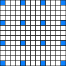
To calculate the values for a given tile requires the corner values of that tile along with the corner values of the eight surrounding tiles — that is, all the blue pixels in the picture are needed to calculate the pixels required to calculate the pixels in the centre tile.

The corner values from one tile effects the calculation of the tiles adjacent.  For this reason, the corner values of each tile are state that must remain constant for the entire frame.

To render a full 1920×1080 frame, 15×9 tiles are required, with 16×10 corner values.  To calculate the tiles around the frame border, further un-rendered tile data is required to correctly seed each of these border tiles.  The result of this is that 18×12 random pixel values are needed to define the full set of tiles for a 1080p frame, which means the seeds for the tiles of a frame can be stored in 18x12x4 = 864 bytes.  Not unreasonable.

When rendering each tile, these seed values are first placed in the appropriate 16 locations (taking into account the compressed outer regions), and the interpolation takes place.  (Interpolation is performed on the seed values and, later, using only values calculated during a previous iteration — which means there’s no requirement to zero memory between tiles)

The result with just this looks quite reasonable (imho) — there’s decent interpolation of random values across the screen.  These random seed values can also be permuted without too much difficulty between frames — I’ve tried some trig-function based methods to give a sense of continuous, directional changes.  It works but I’m sure there’s better options.

As for the random perturbing of interpolated values, I’ve tried a few methods and not achieved anything that I’ve been all that happy with.  The problem I’ve had is finding/generating a suitably random value of appropriate scale, and applying it to the pixel value fast enough.

(As I reach the end of this, I have the impression that what I’ve put together is almost, but not entirely unlike, Perlin noise —  you could possibly say that it has a really clumsy interpolation function.  I have a much better understanding of Perlin noise than when I began, and it really looks like I should have tried that.  Learning is Good.)

At some stage in the not too distant future, I hope to perform some screencaps and post some actual images and maybe even a video.  And fwiw I’ll post the source code, too.

Diamond-Square — DMA lists and dirty tricks

There’s a hole in my dataset, dear MFC, dear MFC…

There’s a block of local store that holds a tile of pixels that need to be DMAd out to main memory.  128 lines makes performing many smaller transfers more complex , so we’ll try DMA lists why not.  The problem here is that the pixel data for each line does not match up directly with the next — between each is stored the extra lines of extra-tile information that was needed for the calculation.  When using DMA lists to transfer data to many memory, the source for each DMA transfer starts where the previous one ended. This means that between each DMA there’s (148-128)×4=80 bytes of information that we don’t want to see on the screen.

There’s a lot of things that are “best-practice” for SPU DMA, particularly relating to size and alignment of transfers, and I’m typically a religious adherent.  In this case, I did not comply with best practice and still met my time budget and only feel a small amount of shame :P

Overall, less time is spent performing DMA than is spent calculating pixels, so further optimising DMA for this particular program is unnecessary.

When transferring tiles from the SPU to the framebuffer, there’s three cases of particular interest:

  1. Tiles on the right edge of the screen
  2. Tiles on the lower edge of the screen
  3. The Other Tiles
Tile data in local store

3. The Other Tiles

These are the easy ones.  They will never need to be trimmed to fit the screen edges, and if drawn in the right order have the wonderful characteristic that the extra data needed can be DMAd to the framebuffer and will be overwritten by pixel data from a later tile.  There’s no special case needed, just draw each pixel line and — all data between pixel lines — to the screen.

Tile data drawn to screen

(For the diagrams, the amount of overdraw is far greater than the actual tile part — this is a consequence of the small size.  It’s a much smaller percentage for 128 pixel tiles.  I’ll post some actual screengrabs here sometime…)

1. Tiles on the right edge of the screen

Overdraw isn’t the answer in this case. It is not possible to overdraw on either the left or right of the rightmost tile in a way that will be correct when the screen is finished.  Instead, the extra information (including any portion that may not fit onto the visible screen) must be dealt with some other way.

My solution, ugly as it is, is to write each surplus portion of a tile to a scratch location in memory — every one of them to the same location.  It works :|

2. Tiles on the lower edge of the screen

These tiles are really just like the others, except they’ll stop a few lines short.  They’re still fully calculated, but only the visible lines are transferred.

(In hindsight, increasing the spacing between lines would help reduce the alignment and size problem here.  Adding an extra 48 bytes to each tile would allow every transfer to be optimally aligned and sized.  And would probably make no measurable difference to the total runtime.  Heck, there’s probably enough time to repack the data in local store before performing the DMA. There’s not that much…)

Diamond-Square — Tiled rendering and space

I started with the assumption of 128×128 pixel diamond-square tiles — they’re a power of two big (which makes them simpler to calculate), 512 bytes wide, 128 lines tall and 64KB in total size, which means two will fit in local store.

So, questions: What points outside this area are required to calculate all the points within?  How much space is required to render one of these tiles?

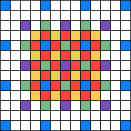
(There’s a smaller example pictured, again with a different colour for each iteration of the calculation)
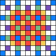
If the tile is to be 4×4, the centre area is 5×5 with overlap between tiles.  Additionally, to calculate a 4×4 tile, fully calculating a 7×7 area is required, not counting the sparsely calculated pixels around the outside.

Scaling this up to 128×128 pixel tiles and it should be clear that at least 131×131 pixel area is required, not counting those extras around the outside.  How to deal with those?

One thing that is clear is that they’re sparsely filled, and that calculated values only appear on certain lines.  In fact, the number of lines required around the outside of a tile is (1+log2n) where n is the tile width.  For the 4×4 tile pictured, three extra lines are needed on each side of the tile.  For a tile 128 lines across, 8 extra lines are needed.

So all the values to calculate a given tile can be stored in in (129+8+8)×(129+8+8) = 145×145 pixels.  Rounding up to get quadword aligned storage gives a total of 148×145×4 bytes — 85,840 bytes per tile.  171,680 bytes is a big chunk of local store, but it’s probably better to be using it for something

Based on that, it’s not particularly difficult to generate the data for a tile.  Start the tile with its starting values (more on those in another post) in the corners of the squares (the blue ones in the picture), and then calculate the remaining points.  There’s some special cases required for each of the sides, but it’s nothing particularly tricky, just keeping track of row/column indexes for particular iterations.

The outer points make up only a very small percentage of the total points that need to be calculated — more than 50% of the points are calculated in the last diamond and square iterations, and due to the proximity and alignment of the points accessed, their calculation can be usefully optimised.  (I might write a post about that sometime…)

Diamond-Square — Data dependency and SPU

To work out a suitable way to divide a 1080p screen into pieces that a SPU could work effectively with for the diamond-square problem took some trial and error.  First, some fundamentals.

DMA

The SPU interacts with the framebuffer through the use of DMA operations, which have the following characteristics:

  • larger transfers are more efficient than smaller ones
  • there are alignment constraints
  • there can be a tradeoff between performing several small transfers to cope with DMA size/alignment constraints, and fetching a larger aligned area, modifying it and writing it back
  • modifying a region of memory requires a DMA get and put operation — extra work, complexity (buffer management and time)
  • a single SPU can have a maximum of 16 transfers in-flight at a given time, and will block if any more are issued
  • DMA lists can be used to effectively issue more than 16 transfers at a time, but there are greater restrictions on the placement of data in local store

Data relationships

To calculate each point in diamond-square required the values from four others.

When calculating the centre point of a square, the four corners are located on two different lines and the centre point is written to the centre line between those two.  (Reading from two lines, writing to one)

When calculating the centre point of a diamond, the four corners are located on three different input lines and the centre point is located on the same centre line as two of the points (Reading from three lines, writing to one of those)

For a given iteration of diamond-square, all input data has been generated in a previous iteration — that is, no point depends on another point calculated in the same iteration of the algorithm.  This gives some flexibility as to the ordering of point calculation.

First attempt — whole lines

My first thought was to optimise for DMA throughput: large transfers are much more efficient than smaller ones, and the independence of points in a single iteration means that points can be calculated on a line by line basis.  Pseudo this:

square(line_number, square_size)
    top = dma_get(line_number)
    centre = dma_get(line_number + square_size/2)
    bottom = dma_get(line_number + square_size)
    for(i = 0; i < line_length; ++i)
        calculate_square_centre_value(top, centre, bottom, i, square_size)
    dma_put(centre)

Whole lines are fetched, which is reasonably efficient (1920×4 bytes = 7680, 7680%128 = 0, so it’s a fine size for efficient DMA), and there’s plenty of scope for optimisation:

  • lines may be prefetched
  • lines may be reused between iterations: the bottom line for one row of squares is the top line of the next.  For diamonds, two lines are reused from one row to the next

I spent quite a bit of time on this approach, to try and get it working to my satisfaction, but in the end I discarded it.  The problem for me became one of complexity — the prefetches, special cases (sides, corners) and line reuse were all written and applied for the general-case implementation (i.e. parameterised by square_size like the pseudo code above). This made it extraordinarily cumbersome to write optimised cases for the smallest square sizes — where most of the pixels are calculated and thus most runtime is spent.

In summary, I was optimising the wrong things.

There were also aspects of the implementation that I had not fully considered with this method, and failed to make progress with, particularly proper handling of the side and corner special cases, and animation.

(In hindsight, I suspect I could have simplified this approach, solved the other problems and met the time budget — but probably only knowing what I know from my next attempt.)

Second attempt — tiles — problems

Tiling was an approach I had considered and discarded early on.  Where whole lines are a clear win for DMA efficiency, tiles are much less so — the largest square tiles I could envision were 128×128 pixels, being 64KB (twice for a double buffered implementation), and the 512B line length is not a great performer.  Additionally, the limit on the number of in-flight DMA transfers makes this method seem more risky — writing 128 lines per tile requires writing lines as the calculation of each is completed and hoping that computation is slower than DMA, which is probable but not assured.

DMA lists are promising — except that diamond-square requires 2n+1 pixel squares, so it’s actually a 129×129 pixel tile (for calculation), and DMA lists still need to transfer those little extra inner parts between transfers.

On top of that, recall that diamond-square requires a large number of points from outside a tile to be calculated to be able to complete the points within a tile — if stored sparsely, 8 times as much space as for the target tile.

So I didn’t start with this idea, but after discarding the previous approach I was able to work out ways around these problems and implement a basic and functional implementation in the time I spent flying and waiting in airports on my way home from GCAP.  I’ll expand on the implementation in a later post.

Diamond-Square — What can you do in 25 cycles?

or “How I got 1080p 60Hz diamond-square plasma from a single SPU”

I am primarily writing this — and subsequent posts — as a record and exercise for myself, and in case there’s anyone who attended the TUCS talk I gave in October that is still interested in the problem and my solution.

I started with a simple (naive) equation:
3.192×10⁹ cycles / (1920×1080 pixels × 60 frames per second) = 25.66 cycles per pixel

That is, to update a 1080p screen at 60Hz, there’s an upper limit of 25 cycles per pixel.

So, what can you do in 25 cycles?

Starting with the simple and obvious: On an SPU, writing to local store takes 6 cycles — that’s a quarter of the time budget gone, right there. DMAing that pixel to the framebuffer in system memory will take hundreds of cycles. Approaching this problem one pixel at a time is clearly not the way to solve it.

Slightly less simple: A write to local store will be six cycles, and it can be pipelined to give four pixels per cycle. A single SPU can do DMA at over 16GB/sec. This should be easy — and it is if all you want to do is write stuff to memory. Throw in some computation and data dependencies and things get a lot more interesting.

So, I chose a problem that is one of my old favorites from Amiga demo days — plasma. There’s a number of ways you can achieve the effect. I chose diamond-square interpolation, which turned out to have some interesting problems to implement for SPU1.

The Diamond-Square Algorithm

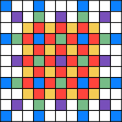
The images here show the process of interpolation used for diamond-square (in these diagrams, each interpolation iteration is displayed with a different colour, not the expected calculated colour):

  • Starting with one or more squares, average the corners (with a random perturbation) of the square to calculate the centre point
  • For the diamonds then created, average the corner points (again, with a random perturbation) to calculate their centres
  • Later, rinse, repeat until all the gaps are filled.

Seems simple enough, but there’s some complexity in the implementation.

Data points and space requirements

For a 9×9 starting grid with 9 points defined, only the innermost 3×3 square is fully filled in. The remaining un-coloured (white) points cannot be calculated without having more starting values available (or using some other special case method to appropriately generate the missing information).

Additionally, it can be seen that generate a 3×3 completed pixel region requires the full 9×9 are to start with. Not particularly space efficient.

Data dependency

To calculate a point requires the points around it to be fully calculated, and each of those requires the four surrounding it.  This also has consequences when considering how to divide the problem when trying to calculate a large bitmap using a single SPU and its 256KB local store.

Animation

Producing the same image 60 times a second is not very interesting, so there should be some way to cause it to change over time, in some continuous fashion, where each frame relates to the last in a visually pleasing fashion. Doing this in practice becomes a question of where the source “random” values come from, and how they can be varied over time.  Additionally, the use and generation of source values relates to how the output space is divided.

I’ve written previously about some of the issues I encountered when writing this (fast averaging, system calls, poorly performing first frame), and I intend to write about the three areas mentioned above (space requirements, data dependency and animation).

1Additionally, there’s better ways to create the plasma effect. I did it all again, I’d start with Perlin noise, which appears to still have some interesting challenges but is overall better suited to the hardware.

1

Assembly Primer Part 7 — Working with Strings — SPU

These are my notes for where I can see SPU varying from ia32, as presented in the video Part 7 — Working with Strings.

The ia32 instructions covered in this video (MOVSx, LODSx, STOSx, CMPSx, CLD, STD) clearly highlight many of the differences between that arch and SPU:

  • Implied operand registers e.g. MOVSx using %esi and %edi as source and destination addresses.
  • Side effects on operands e.g. incrementing addresses while performing reads/writes
  • Side effects in the FLAGS register e.g. direction flag, zero flag
  • Support for any alignment of data.

I’ve made less effort to re-implement the full functionality of the ia32 instructions for this part.  There’s a couple of cases that might be interesting to attempt to do so, but a fully general case can probably just be lifted from newlib’s memcpy() implementation for SPU.

Again,  this is the quick SPU instruction reference I use, and I still regularly refer to the SPU ISA doc.

Working with Strings

Starting with StringBasics.s, firth there’s some storage:

 1 .data
 2     .align 4
 3     HelloWorldString:
 4         .asciz "Hello World of Assembly!"
 5     .align 4
 6     H3110:
 7         .asciz "H3110"
 8     .align 4
 9     shuf_AABABCDghijklmnop:
 10         .int 0x00000100,0x01020317,0x18191a1b,0x1c1d1e1f
 11 #.bss
 12     .comm Destination, 100, 16
 13     .comm DestinationUsingRep, 100, 16
 14     .comm DestinationUsingStos, 100, 16

Notable changes from the original:

  • Added .align 4 before each label to provide 16 byte alignment
  • There’s a shuffle pattern added that I’ll write more about later
  • .bss is commented out because spu-as doesn’t like it (I’m still not clear on why this is the case)
  • spu-as doesn’t support alignment for .lcomm but does for .comm (why?), so .lcomm has been replaced with .comm and the trailing “, 16” added to each case to provide 16 byte alignment.
    (learned: .align doesn’t have an effect on .comm/.lcomm, and .comm’s alignment isn’t power of 2, à la .align — there’s nothing hard about assembly programming, really :\)

1. Simple copying using movsb, movsw, movsl

 26         #movl $HelloWorldString, %esi
 27         #movl $Destination, %edi
 28
 29         ila $5,HelloWorldString
 30         ila $6,Destination
 31
 32         #reverse order of instructions to avoid even sillier alignment hassle
 33         #movsw
 34         lqd $7,0($5)
 35         lqd $8,0($6)
 36         rotqby $10,$7,$9
 37         cwd $11,0($6)
 38         shufb $12,$10,$8,$11
 39         stqd $12,0($6)
 40         ai $5,$5,4
 41         ai $6,$6,4
 42
 43         #movsl
 44         lqd $7,0($5)
 45         lqd $8,0($6)
 46         ai $9,$5,-2     # rotate needed to get val into pref slot
 47         rotqby $10,$7,$9
 48         chd $11,0($6)
 49         shufb $12,$10,$8,$11 # shuffle byte into dest
 50         stqd $12,0($6)
 51         ai $5,$5,2
 52         ai $6,$6,2
 53
 54         #movsb
 55         lqd $7,0($5)
 56         lqd $8,0($6)
 57         ai $9,$5,-3     # rotate needed to get val into pref slot
 58         rotqby $10,$7,$9
 59         cbd $11,0($6)
 60         shufb $12,$10,$8,$11 # shuffle byte into dest
 61         stqd $12,0($6)
 62         ai $5,$5,1
 63         ai $6,$6,1

Of the examples in this part, this is my biggest attempt at a “complete” implementation of the ia32 instructions, and even then it’s built on the assumption of natural alignment (of words and halfwords) not present in the ia32 code.  Lots of effort to achieve some simple tasks.

Making the extra assumption that the alignment of source and destination match, the three MOVS instructions can be combined and simplified to something like:

 66         lqa $13,HelloWorldString
 67         lqa $14,Destination
 68         fsmbi $15,0x01ff
 69         selb $16,$13,$14,$15 # copy only desired bytes into destination vector
 70         stqa $14,Destination

With the further assumption that the destination was able to be trashed entirely, this could be reduced to just a load and a store.

2. Setting / clearing the DF flag

There is no DF flag.  It could be simulated through the use of an offset stored in another register that is added to addresses using lqx & stqx instructions, which would achieve the same kind of functionality.

3. Using Rep

REP is a fascinating little instruction (modifier? Appears to be a single byte in disassembly), but there’s no direct equivalent for the SPU.  It could be mimicked in a general way on SPU using branches, but branches are a topic of later parts in the series so I’ll avoid that for now.

Instead, because the length and alignments of source and destination are known, it can be (effectively) unrolled and branchless :)

 85         #movl $HelloWorldString, %esi
 86         #movl $DestinationUsingRep, %edi
 87         #movl $25, %ecx # set the string length in ECX
 88         #cld # clear the DF
 89         #rep movsb
 91
 95         lqa $20,HelloWorldString
 96         lqa $21,HelloWorldString+16
 97         lqa $22,DestinationUsingRep+16
 98         fsmbi $23,0x007f
 99         selb $22,$21,$22,$23
100         stqa $20,DestinationUsingRep
101         stqa $22,DestinationUsingRep+16

A simple load and store for the first quadword, and a merge of the second with its destination.  Again, making further assumptions about the destination memory would remove the need for lines 97–99.

4. Loading string from memory into EAX register

106         #leal HelloWorldString, %esi
107         #lodsb
112         ila $24,HelloWorldString
113         lqa $25,HelloWorldString
114         ai $26,$24,-3
115         rotqby $27,$25,$26
116
117         #dec %esi
118         #lodsw
120         ai $28,$24,-2
121         rotqby $29,$25,$28
122
125         #subl $2, %esi # Make ESI point back to the original string
126         #lodsl
128         rotqby $30,$25,$24

Similar to 1. — loading data and rotating into the preferred slot of a register.  Assumptions about source offset and that the loaded data doesn’t span a quadword boundary makes this much simpler than it would otherwise be.

5. Storing strings from EAX to memory

  8     .align 4
  9     shuf_AABABCDghijklmnop:
 10         .int 0x00000100,0x01020317,0x18191a1b,0x1c1d1e1f

133         #leal DestinationUsingStos, %edi
134         #stosb
135         #stosw
136         #stosl
137
141         lqa $31,DestinationUsingStos
142         lqa $32,shuf_AABABCDghijklmnop
143         shufb $33,$30,$31,$32
144         stqa $33,DestinationUsingStos

Rather than more repetitive merging and messing about, I chose to combine the three stores and get the same effect from a single shuffle — which includes merging with the contents of the destination quadword.

(The shuffle name reveals the intended function: capital letters refer to bytes from the first register, lower-case from the second.  I picked up this scheme from Insomniac Games’s R&D pages.)

6. Comparing strings

149         #cld
150         #leal HelloWorldString, %esi
151         #leal H3110, %edi
152         #cmpsb
153
154         lqa $34,HelloWorldString
155         lqa $35,H3110
156         ceqb $36,$34,$35

There’s no byte-subtraction instruction for SPU, but ceqb will compare the bytes in two registers for equality.  That should be enough to work out if two strings match, but doesn’t give the kind of ordering that you’ll get from strcmp().   Getting the result from ceqb and making some kind of use of it may require shifts, rotates or other shenanigans.

Jaymin Kessler has a post on scanning through pixel values that is also relevant for a number of string manipulation problems.

Previous assembly primer notes…

Part 1 — System Organization — PPCSPU
Part 2 — Memory Organisation — SPU
Part 3 — GDB Usage Primer — PPC & SPU
Part 4 — Hello World — PPCSPU
Part 5 — Data Types — PPC & SPU
Part 6 — Moving Data — PPCSPU

Assembly Primer Part 6 — Moving Data — SPU

These are my notes for where I can see SPU varying from ia32, as presented in the video Part 6 — Moving Data.

SPU and ia32 differ significantly when it comes to moving/copying data around, in terms of the ways things can be copied, the alignment of data in memory and the vector nature of SPU registers.

This is the quick SPU instruction reference I use.  The SPU ISA doc is worth having nearby if trying to do silly tricks with SPU instructions.

Moving Data

Lets consider what MovDemo.s might look like for SPU, piece by piece.

First, the storage:

# Demo program to show how to use Data types and MOVx instructions 

.data
    HelloWorld:
        .ascii "Hello World!"

    ByteLocation:
        .byte 10

    Int32:
        .int 2
    Int16:
        .short 3
    Float:
        .float 10.23

    IntegerArray:
        .int 10,20,30,40,50

Icky.  Not naturally aligned for size, and crossing qword boundaries.  This makes the following code particularly messy, because the SPU really doesn’t like unaligned data.  Oh well, let’s begin.

1. Immediate value to register

    .align 3  # ensure code is aligned after awkwardly arranged data
.text
    .globl _start
    _start:
        #movl $10, %eax
        il $5, 10

Well, that was easy enough.

It does get a little trickier if trying to load more complex values.  To load a full 32-bits of immediate data into a register requires two half-word load  instructions for the upper and lower parts.

Loading arbitrary values spanning multiple words is more complex, and is often able to be done simply by storing the constant in .rodata and loading it when needed, although fsmbi can be useful on occasion.

2. Immediate value to local store

#movw $50, Int16

# Write first byte
ila $6,Int16        # load the address of the target
lqa $7,Int16        # load the qword
il $8,0             # load the upper byte of the constant into preferred slot
cbd $9,0($6)        # insertion mask for higher byte
shufb $10,$8,$7,$9  # shuffle the upper byte into the qword
stqa $10,Int16      # write the word back
# Write second byte
il $11,1            # load 1 for address offsetting
cbd $12,1($6)       # insertion mask for lower byte
il $13,50           # load the lower byte of the constant into preferred slot
lqx $14,$6,$11      # load Int16+1
shufb $15,$13,$14,$12 # shuffle lower byte into qword
stqx $15,$6,$11     # write back qword

Writing two bytes to a non-aligned memory location is a messy business.

  • All loads and stores transfer 16 bytes of data between registers and 16-byte aligned memory locations.
  • The chd instruction, used to generate masks to be used to shuffle halfwords into a quadword assumes that the halfword is aligned in the first place.  As it is not, and could be crossing a quadword boundary, I write it here as two bytes.

The lqa instruction (a-form) is used for the first load, to fetch from an absolute local store address.  lqx (x-form) is used for the second load, because the address needs to be offset by one — on first glance, lqa and lqd appeared to be better choices, but these do not store all of the lower bits of the immediate part to be used, which would have prevented the one-byte offset.  So x-form is used as the zeroing of lower bits happens after the addition of the preferred word slots of two registers.

I suspect that this can be done better.

(It’s worth taking a look at Jaymin’s post on write-combining which looks more deeply at this kind of problem)

3. Register to registers

#movl %eax, %ebx
ori $16, $5, 0

Using the Or Immediate instruction to perform a bitwise Or against zero to perform the copy.  This can be achieved using the odd pipeline with a quadword shift or rotate immediate instruction.

Copying smaller portions of a register will require extra instruction(s) for masking or rotation, depending on what exactly needs to be copied and to where.

4. Local store to register

#movl Int32, %eax

ila $16,Int32       # load the address
lqa $17,Int32       # load the vector containing the first part
lqa $18,Int32+3     # load the vector containing the second part
fsmbi $19,0xf000    # create a mask for merging them
rotqby $20,$17,$16  # rotate the first part into position
rotqby $21,$18,$16  # rotate the second part into position
rotqby $22,$19,$16  # rotate the select mask into position
selb $23,$20,$21,$22 # select things into the right place.

This one is a different class of fun – loading four bytes that span two quadwords.  Using fsmbi to generate a mask that is used to combine bytes from the two quadwords.

Again, I suspect there’s a better way to do it.

5. Register to local store

#movb $3, %al
#movb %al, ByteLocation

ila $24,ByteLocation
lqa $25, ByteLocation
il $26,3
cbd $27, 0($24)
shufb $28, $26, $25, $27
stqa $28, ByteLocation

Essentially the same problem as 2. on the SPU, but a little simpler because it’s only a single byte.

6. Register to indexed memory location

#movl $0, %ecx
#movl $2, %edi
#movl $22, IntegerArray(%ecx,%edi , 4)
il $29,2                # load the index
ila $30,IntegerArray    # load the address of the array
shli $31,$29,2          # shift two left to get byte offset
lqx $32,$30,$31         # load from the sum of the two addresses
# and then write the data to memory...

This is an attempt at a comparable indexed access to local store.  All I’ve done here is the address calculation and load — writing the value is a mess because it’s not aligned and spans two quadwords, so something like that done in 2. would be required.

7. Indirect addressing

movl $Int32, %eax
movl (%eax), %ebx

movl $9, (%eax)

I’ve done these before (essentially) in 2. and 4.

Concluding thoughts

Align your data for the SPU.  This would have all been much, much simpler (and not much of a challenge) if the data was aligned and variables were in preferred slots.  I suspect I’ll simplify the later parts of the series for SPU by aligning the data first.

I found some useful fragments amongst the Introduction to SPU Optimizations presentations from Naughty Dog — they’re a very good read: Part 1 & Part 2.

Previous assembly primer notes…

Part 1 — System Organization — PPCSPU
Part 2 — Memory Organisation — SPU
Part 3 — GDB Usage Primer — PPC & SPU
Part 4 — Hello World — PPCSPU
Part 5 — Data Types — PPC & SPU

Assembly Primer Part 5 — Data Types

These are my notes for where I can see both PPC and SPU varying from ia32, as presented in the video Part 5 — Data Types.  There’s not a lot to be said about this one, so there’s just the one post for both PPC and SPU architectures.

The main problem with assembling the provided VariableDemo.s is that gas doesn’t seem to like the .bss section for either PPC or SPU, producing an error.  To be able to assemble this file on these architectures, I removed the .bss line and (obviously) removed (replaced) the ia32 asm instructions.  objdump shows that “.comm LargeBuffer 10000” is placed in .bss, as intended.

(At this point, I’m quite out of my depth as to why this difference between the architectures exists — if someone can enlighten me, that’d be great :)

I was interested to see that gdb has no problem accessing the unaligned variables on the SPU.  It’s worth noting that the assembler is quite happy to let you place data wherever you like (with great power comes great etc.).  And I think I need to take a closer look at the .align directive.

Previous assembly primer notes…

Part 1 — System Organization — PPC — SPU
Part 2 — Memory Organisation — SPU
Part 3 — GDB Usage Primer — PPC & SPU
Part 4 — Hello World — PPCSPU

Assembly Primer Part 4 — Hello World — SPU

These are my notes for where I can see SPU varying from ia32, as presented in the video Part 4 — Hello World.

I’ve written about syscalls on SPU before, here.  System calls can be performed using appropriately packed data and stopcode 0x2104, which is intercepted by the kernel.

The JustExit.s example in the video uses the exit syscall, which is explicitly excluded from being called by the SPU.  For the sake of the example, we can use the time syscall instead, and so a simple syscall looks something like this:

.data
syscall_time:
    .quad 13 # syscall number and return value
    .quad 0  # parameters
    .quad 0
    .quad 0
    .quad 0
    .quad 0
    .quad 0

.text
.globl _start
_start:
    stop 0x2104
    .int syscall_time

syscall_time is the structure used by the syscall (see struct spu_syscall_block and __linux_syscall()) with 13 in the first unsigned long long. (“Obviously”, .quad is 8 bytes :\).  If there were arguments to pass to the syscall, they would be placed in the six following .quads.

The address of the syscall block must follow directly after the stop instruction.  (I did wonder if there would be some trick to mixing the address with the program code — as you can see, no trick needed)

The syscall’s return value is placed in the first 8 bytes of the syscall block.

While it’s possible to use the write syscall, it’s rather painful as it requires a valid char* ea to be passed to be written, which is not readily accessible from the SPU.  The alternative is to use the __send_to_ppe() function — write() is one of the POSIX1 functions handled by newlib+libspe.  Of course, it has a slightly different calling mechanism to to __linux_syscall(), uses the JSRE_POSIX1 stopcode of 0x2101.  This works:

.data

HelloWorldString:
    .ascii "Hello world\n"

send_to_ppe_write:
    .int 1 # stdout
    .int 0 # pad
    .int 0 # pad
    .int 0 # pad
    .int HelloWorldString # char* in local store
    .int 0 # pad
    .int 0 # pad
    .int 0 # pad
    .int 12 # length
    .int 0 # pad
    .int 0 # pad
    .int 0 # pad

.text
.globl _start

_start:
    stop 0x2101
    .int send_to_ppe_write+0x1b000000

Although I’m sure it can be expressed more elegantly.

The magic number 0x1b000000 added to the address of send_to_ppe_write is derived from the “combined” variable from __send_to_ppe() with the values from jsre.h.

Alternatively…

I just realised that this works: if /proc/sys/kernel/randomize_va_space is zero, the address of the mapped SPU LS (from /proc/$PID/maps, as seen here) of 0xf7f70000 can be used as an offset to anything in local store, so the syscall will work with offset pointers:

.data

HelloWorldString:
    .ascii "Hello World\n"

syscall_write:
    .quad 4 # write
    .quad 1 # stdout
    .int  0 # gas doesn't seem to like doing the arithmetic in a .quad
    .int 0xf7f70000 + HelloWorldString # mapped address of string
    .quad 12 # length
    .quad 0
    .quad 0
    .quad 0

.text

.globl _start

_start:
    stop 0x2104
    .int syscall_write

Hideous :)

Previous assembly primer notes…

Part 1 — System Organization — PPC — SPU
Part 2 — Memory Organisation — SPU
Part 3 — GDB Usage Primer — PPC & SPU